This page is provided by TECI and gives
you the information to create both standard and reverse patch
cable wiring diagrams.
RJ-45 Standard Patch
Cable Wiring Diagram
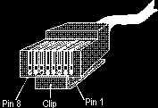
If you hold the RJ-45 connector facing
you (as if you were going to plug it into your mouth) with the lock
tab/clip on the bottom, the pins are numbered 8 to 1 from left to
right. The pin usage should be the same for both ends of the cable and
is as follows:
|
Standard Patch Cable (Both Ends) |
|
Pin Number |
Assignment |
Color |
|
1 |
Output Data (+) |
orange/white |
|
2 |
Output Data (-) |
orange solid |
|
3 |
Input Data (+) |
green/white |
|
4 |
Reserved for Telephone use |
blue solid |
|
5 |
Reserved for Telephone use |
blue/white |
|
6 |
Input Data (-) |
green solid |
|
7 |
Reserved for Telephone use |
brown/white |
|
8 |
Reserved for Telephone use |
brown solid |
If you don't follow this exact wiring or
color scheme, you should at least wire your cable so that the two
output data conductors (1 & 2) make up one twisted pair and the two
input data conductors (3 & 6) make up another twisted pair. (One
"pair" consists of two twisted wires: One wire is solid colored; the
other wire is the same color, but has a white stripe [orange
solid &
orange/white
are a pair]). If the cable is not paired
correctly (mixing colors or mistakenly using 3 & 4 on one pair and 5 &
6 on another pair or splitting the assignment types between pairs), it
may work for lengths less than a meter, but will fail miserably
for longer lengths.
RJ-45 Crossover Patch
Cable Wiring Diagram
If you are connecting two machines to
each other, it is possible to avoid using a hub by swapping the output
data and input data pairs (1 & 2 swapped with 3 & 6, respectively).
This change is all that's required to make a crossover cable. One end
is wired as if the cable was going to be a standard patch cable, while
the other end is wired with the input data and output data pairs
swapped. This swap feeds the output data of one (local) computer to
the input data of the second (distant) computer, and vice-versa. In
other words, the orange and green pairs are switched at one of the
ends. The polarity at the switched end remains unchanged (stripes are
still strips and solids are still solids). The pin usage for each end
of the cable is as follows:
|
Crossover Patch Cable (RJ-45 End at
Local Computer) |
|
Pin Number |
Assignment |
Color |
|
1 |
Output Data (+) |
orange/white |
|
2 |
Output Data (-) |
orange solid |
|
3 |
Input Data (+) |
green/white |
|
4 |
Reserved for Telephone use |
blue solid |
|
5 |
Reserved for Telephone use |
blue/white |
|
6 |
Input Data (-) |
green solid |
|
7 |
Reserved for Telephone use |
brown/white |
|
8 |
Reserved for Telephone use |
brown solid |
|
Crossover Patch Cable (RJ-45 End at
Distant Computer) |
|
Pin Number |
Assignment |
Color |
|
1 |
Input Data (+) |
green/white |
|
2 |
Input Data (-) |
green solid |
|
3 |
Output Data (+) |
orange/white |
|
4 |
Reserved for Telephone use |
blue solid |
|
5 |
Reserved for Telephone use |
blue/white |
|
6 |
Output Data (-) |
orange solid |
|
7 |
Reserved for Telephone use |
brown/white |
|
8 |
Reserved for Telephone use |
brown solid |
Again, if you don't follow this exact wiring or
color scheme, you should at least wire your cable so that each data
channel (its positive and negative signals) uses both conductors of a
twisted pair. If the cable is not paired correctly, it may work for
lengths less than a meter, but will fail miserably for longer
lengths.
|